Intelligent Marine Traffic Management Systems: What Actually Moves the Needle on Safety and Efficiency
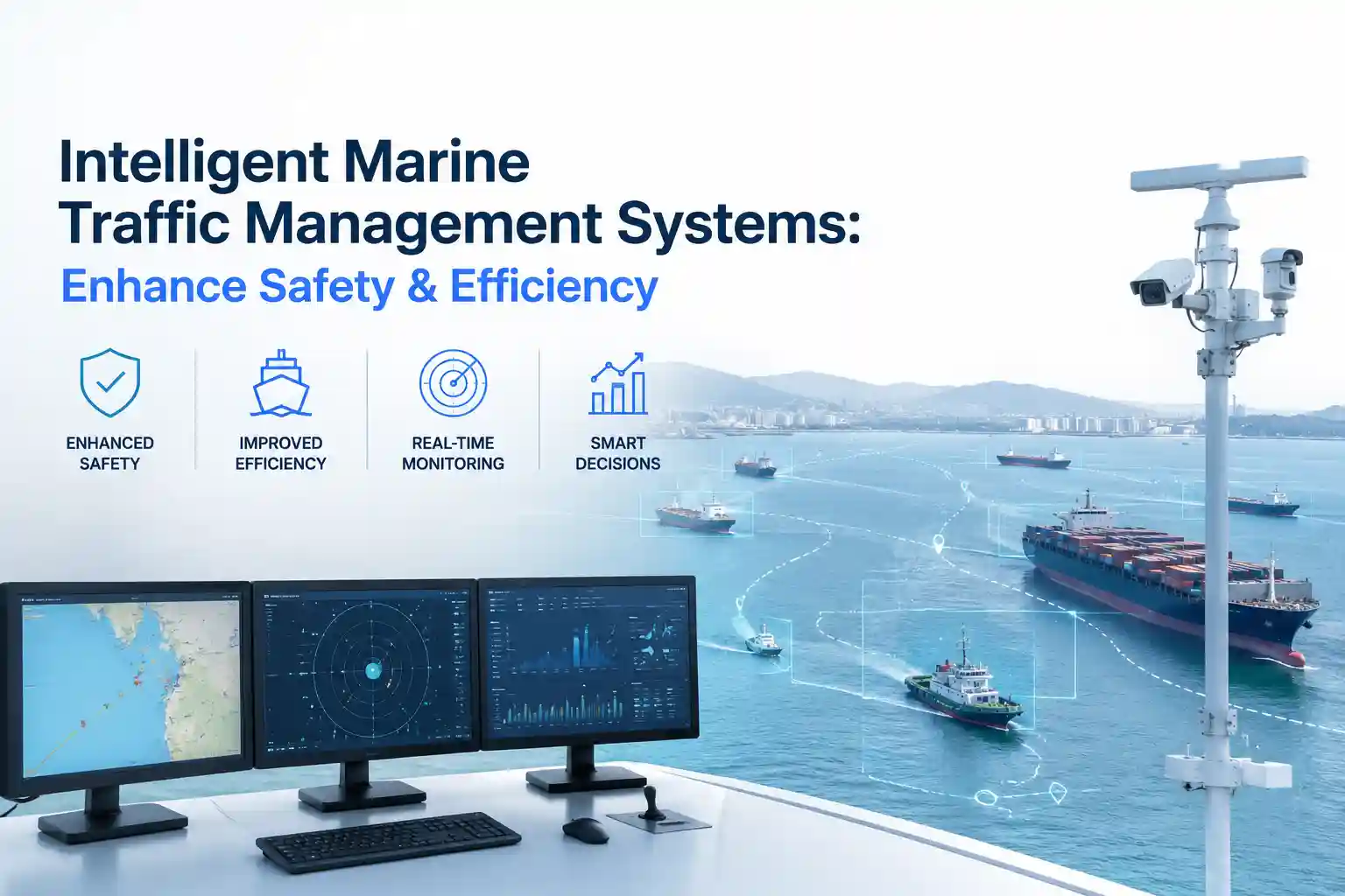
The VTS operator console displayed a clean convergence window. Three tankers, a bulk carrier, and a coastal ferry were projected to clear the main shipping channel within a forty-minute span. The intelligent marine traffic management systems: enhance safety & efficiency algorithms had already calculated optimal separation distances, factored in tidal current vectors, and pushed staggered pilot boarding recommendations to each bridge team. On the primary monitor, the routes intersected at safe angles. The conflict-resolution pane stayed quiet. Everything looked engineered.
Then a squall line dropped out of a low-pressure trough. Rain cells fractured the X-band radar return. Wind shifted from three-one-zero to two-eight-zero in under four minutes, pushing surface currents sideways across the planned approach lines. The system kept drawing smooth, predicted tracks because the latest AIS position packets arrived with a sixty-second transmission lag. The ferry captain, reading the actual water, called in a ten-knot speed reduction. The traffic management algorithm didn’t register the deceleration for ninety seconds. For a brief window, the console showed a safe passage while two vessels were actually closing at reduced separation in heavy weather.
The operator didn’t panic. They muted the proximity advisory, picked up the VHF handset, and started talking directly to the bridges. The dashboard went quiet. The conversation took over. That gap between algorithmic prediction and real-time hydrodynamic reality isn’t a software failure. It’s the operational baseline of modern marine traffic coordination. The systems work, but they work best when treated as decision support rather than autonomous directors. Once you bolt them to rolling antennas, route power through vibrating conduit, and expose them to salt-laden air that shifts with the tide, the clean data streams start behaving like everything else in a working waterway: they require constant human verification.
When the Data Stream Meets the Water
Hardware specifications look solid on procurement sheets. IP66 enclosures, MIL-STD shock ratings, extended operating temperature ranges, redundant power feeds. In a VTS tower or onboard bridge installation, those specifications meet continuous thermal cycling, electromagnetic interference from nearby radar scanners, and the specific low-frequency vibration of diesel auxiliary generators running at varying loads. I’ve reviewed antenna mounts where the conformal coating held up perfectly, but the coaxial strain relief had micro-cracked from constant cable flex. Moisture didn’t short the board immediately. It crept in, condensed, and bridged pins during a rapid temperature drop when a cold front pushed through the harbor at midnight.
The gateway didn’t crash. It just started dropping AIS sentence blocks until a manual power cycle cleared the buffer. Shore-side monitoring saw a temporary vessel dropout. The watch officer saw routine radar confirmation and adjusted the watch plan accordingly.
Installation delays rarely come from missing components. They come from spatial constraints and legacy wiring congestion. You can’t run fiber optic backbones parallel to high-voltage radar waveguide routes without introducing signal degradation. You can’t mount secondary surveillance antennas too close to the main mast without creating multipath interference. You can’t expect thermal paste to maintain conductivity on server rack heat sinks when ambient humidity stays above eighty percent for three months straight. Every routing decision is a compromise between ideal signal fidelity and the physical reality of existing vessel or tower architecture.
Operators adapt quickly, though rarely in ways that align with vendor documentation. I’ve seen VTS workstations mounted on custom vibration-dampening brackets because the standard wall plates transmitted too much structure-borne noise into the hard drives. I’ve watched technicians reroute grounding cables away from cathodic protection anodes after stray currents introduced voltage drift into the sensor network. These aren’t deviations from standard procedure. They’re practical workarounds for keeping the system stable in an environment that actively degrades precision electronics.
Salt exposure doesn’t announce itself with immediate failure. It oxidizes unused DIN rail terminals. It bridges unshielded connector pins during heavy spray events. It accumulates in ventilation filters until cooling fans work harder, driving rack temperatures past optimal thresholds. Maintenance cycles that look reasonable on quarterly checklists compress rapidly when a waterway runs at high utilization for extended periods. The hardware survives. It just demands more physical intervention than the deployment manual suggests.
Simulating Congestion and System Latency
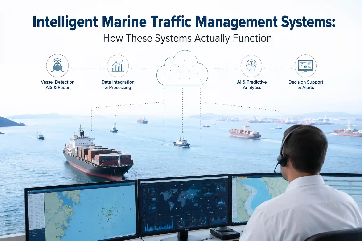
I ran a localized traffic stress test using buffered AIS refresh intervals and artificially delayed radar target fusion to mimic real-world communication degradation during peak congestion. The setup wasn’t designed to break the hardware. It was meant to observe how quickly stale positional data becomes operationally misleading when the management console attempts to fill tracking gaps with predictive routing algorithms.
Within six minutes of simulated uplink throttling, the traffic coordination platform began smoothing vessel trajectories based on the last received speed-over-ground values. The actual vessels were maneuvering through shifting tidal eddies, adjusting rudder angle incrementally to maintain channel alignment against lateral drift. The dashboard drew a clean, optimized convergence. The control center almost broadcast a revised sequencing order. I had to flag the data window, pull raw radar screenshots from the primary array, and cross-reference them with bridge voice logs before the operator made a routing call.
The discrepancy didn’t come from faulty sensors. It came from software assuming consistent hydrodynamic resistance when the environment was actively changing. Predictive sequencing performs reliably in stable, low-traffic channels. It struggles when wind, current, and pilot decisions alter vessel behavior faster than the reporting interval can capture.
Software friction compounds during high-traffic periods. When dozens of vessels share the same tracking workspace, interface clutter becomes a real operational constraint. Alerts trigger simultaneously for course deviation, speed variance, draft restriction flags, and restricted maneuverability status changes. You scroll past two dozen status indicators to locate the one parameter that actually dictates safe passage in reduced visibility. The console doesn’t fail. It just demands more situational processing capacity than a single controller can reasonably maintain during active navigation sequencing.
The most effective setups don’t push every available metric to the primary display. They filter aggressively. They suppress routine fluctuations. They prioritize deviations that exceed established safety thresholds. The rest sits in local buffers for post-transit review. It’s a less visually complete approach, but it prevents alert fatigue from masking genuine conflict situations.
Who Actually Extracts Value from These Networks
The operators who get practical returns from integrated traffic coordination aren’t reading vendor whitepapers. They’re the fleet dispatchers who cross-reference historical transit times with tidal current charts, then wash the data against seasonal weather patterns to identify bottleneck periods. They understand that the traffic management layer isn’t an autonomous commander. It’s an auxiliary coordination tool that supports sequencing when calibrated to actual waterway conditions.
VTS staff rarely treat these dashboards as primary decision engines unless the alert thresholds match real navigational tolerances. If a proximity warning triggers every time a vessel adjusts speed within normal pilot maneuvering ranges, it gets muted. Permanently. Deployment resistance rarely comes from skeptical controllers. It comes from systems that demand more screen verification than the watch rotation allows, and more diagnostic follow-up than the technical support schedule accommodates.
Training isn’t a three-day certification course. It’s four to six months of adjusting alert bands, watching what actually causes false conflict alarms, and accepting that a significant portion of automated flags stems from antenna placement or multipath distortion, not actual navigational errors. The learning curve isn’t steep, but it’s persistent. You need operators who understand the difference between a genuine tracking anomaly and an environmental artifact. You need technical staff who can trace a corrupted position packet back to a fatigued coaxial bulkhead connector or a misconfigured NMEA router.
Infrastructure requirements scale faster than most budgets anticipate. High-gain surveillance arrays require stable mounting points and clear horizon lines. Older VHF communication towers on mid-sized ports prioritize voice traffic and basic AIS repeaters over high-bandwidth sensor telemetry, starving the traffic management system during peak channel usage. Land-based radar works reliably within visual range of the shoreline, then experiences multipath interference past headland obstructions. Hybrid tracking architectures solve the coverage gap, but they add configuration complexity, additional failure points, and a heavier diagnostic load for maintenance crews.
The operational cost rarely breaks even on routing optimization alone. The real return comes from reduced near-miss incidents, earlier detection of vessel drift, and better channel utilization data during peak seasons. But those benefits only materialize when the system is woven into existing watch procedures, not bolted onto them as a secondary monitoring layer.
Coastal Routing vs. Open-Water Channel Behavior
Coastal operations compress the error margin. You’re within terrestrial radar coverage most of the day. VHF repeater stations bounce off coastal topography, and AIS updates arrive in near-real time. The traffic management system mostly sits in standby mode, logging transit sequences, recording bridge clearances, and tracking vessel speed profiles. Software behaves predictably. Hardware stays dry behind enclosed tower glass. Maintenance intervals align with scheduled port downtime.
Push beyond the coastal shelf or into tidal straits with strong current gradients, and the entire coordination paradigm shifts. Satellite-linked tracking stretches transmission intervals during constellation handovers. Chop and swell mask acoustic positioning backups. Pitch and roll introduce measurement noise that requires aggressive digital filtering. Older transponder arrays on commercial workboats run on legacy serial protocols at 4800 baud, which chokes when you try to push high-frequency environmental sensor data through outdated multiplexers.
Automated sequencing performs adequately when the waterway behaves predictably. Manual oversight becomes the operational backup when it doesn’t. I’ve seen hybrid control setups where VTS operators keep paper traffic logs during heavy weather because the automated conflict-resolution timeline smoothed out the speed adjustments caused by strong cross-currents. The system didn’t malfunction. It just averaged the data in a way that erased the immediate navigational reality.
Commercial traffic coordination platforms handle these conditions better than recreational-grade tracking networks, but only incrementally. Commercial systems include stronger error correction, redundant power distribution, and wider operating temperature tolerances. They still struggle with antenna misalignment during sustained high winds, and they still suffer from firmware patches that occasionally break legacy position parsers. The difference is that trained VTS staff know how to roll back a software update while keeping the primary array operational. Mid-tier port operators usually don’t.
Legacy infrastructure compounds these limitations. Control towers built before the early 2010s rarely have dedicated data routing channels. You tap into existing radar video feeds, splice into VHF logging circuits, and hope the signal isolation holds. It usually does, until thermal expansion shifts a grounding plane and introduces voltage fluctuation. You don’t identify the drift until historical transit logs stop matching current tracking records. By then, you’ve been operating on skewed timing data for weeks.
Why the Tracking Plateau Exists
Marine operational logic doesn’t translate directly into digital sequencing models. A vessel isn’t a static coordinate. It’s a dynamic mass responding to hull resistance, propeller slip, fuel stratification, and continuous helm input. When a traffic management console reports a sudden speed deviation, the algorithm looks for a routing conflict. The pilot knows the vessel has just adjusted pitch to compensate for a localized wind shear. The software lacks a hydrodynamic context. It reports what it receives, not what it interprets.
Infrastructure limitations amplify the discrepancy. Radar constellations promise near-continuous coverage, but antenna rotation on exposed towers introduces signal dropouts during heavy precipitation. Those dropouts aren’t logged as system failures. They register as temporary tracking gaps. The management console fills them with projected vectors. The vessel was actually crabbing through a counter-current. The display draws a straight approach line.
Hardware degradation is rarely sudden. It’s incremental. A corroded coaxial shield, a fatigued bulkhead connector, a fouled radar dome coating, a stretched tension mount on a secondary transponder. Each element degrades signal fidelity just enough that the tracking platform starts averaging instead of reflecting. Control staff adapt by layering manual verification, but manual verification adds staffing overhead and another set of cross-check protocols that compress during peak transit windows.
Communication reliability fluctuates with atmospheric pressure and precipitation density. Heavy rain cells attenuate microwave returns. High sea states scatter radar lobes. Solar interference disrupts ionospheric backup frequencies. The coordination system doesn’t crash during these conditions. It just operates at reduced resolution, broadcasting confirmed positions while the rest sits buffered until the next clear scan cycle.
Human workflow adaptation is the only mechanism that bridges the data gap. Controllers learn to read the console skeptically. They verify critical conflict alerts with voice confirmation. They ignore routine speed fluctuations that fall within standard pilot adjustment ranges. They log positional discrepancies manually when the software smooths out real-time hydrodynamic shifts. It’s inefficient on deployment spreadsheets. It’s necessary in practice.
Recent maritime engineering studies from coastal research stations align with these observations. Tracking accuracy reviews consistently note that automated conflict detection performs best when calibrated to specific waterway geometries, current profiles, and seasonal traffic densities. Universal alert thresholds generate false conflict warnings at unsustainable rates. The marine environment introduces acoustic and electromagnetic noise that laboratory validation rarely captures. NOAA coastal buoy datasets and tidal current modeling studies confirm how environmental variables distort sensor returns when tracking algorithms don’t filter for wave-induced vessel yaw and pitch.
Documented Friction Points
The operational friction accumulates in the antenna housing and on the control screen. It’s rarely dramatic. It’s persistent.
Salt creep along unsealed DIN rail terminals causes phantom voltage readings that trigger low-signal warnings. Fiber runs routed near radar waveguides soften over eighteen months, requiring replacement during scheduled maintenance windows. Dashboard clutter becomes a tangible constraint when every vessel subsystem publishes status flags to the central coordination interface. You’re scrolling past draft measurements, AIS class designations, and propulsion load indicators to locate the one parameter that actually dictates safe clearance during reduced visibility.
Software patches deploy during low-traffic periods, but firmware updates occasionally disrupt legacy position parsers, forcing technical contractors to roll back configurations while vessels wait at holding areas. Sensor degradation on secondary transponder mounts shows up as gradual positional drift that only gets caught during post-transit audit reviews. The learning curve isn’t steep, but it’s continuous. Control staff spends more time filtering false conflict alerts than responding to actual navigational deviations.
Corrosion doesn’t wait for warranty expiration dates. It exploits every unsealed connector interface, every improperly routed grounding wire, every mounting bracket that vibrates against structural steel. Maintenance overhead scales non-linearly once you exceed the manufacturer’s recommended environmental tolerance. Inconsistent tracking emerges when radar refresh intervals collide with heavy precipitation masking antenna arrays. Weather interference isn’t an exception. It’s the operational baseline.
Unreliable position updates compound console frustration. When the system refreshes every twelve seconds during optimal line-of-sight conditions, then drops to twenty-second intervals during atmospheric attenuation, the management platform starts displaying stale approach vectors that conflict with bridge chart displays. Operators adapt by relying on local radar verification over remote tracking portals. It’s a rational adjustment, but it undermines the original deployment objective.
Installation delays rarely stem from missing hardware. They come from structural geometry constraints, existing wiring congestion, and the reality that retrofitting a tracking layer onto an active waterway means coordinating shutdowns with port authorities, testing signal isolation, and recalibrating baseline sensor arrays. You can’t just activate the network and assume stability. You have to integrate it into an operational ecosystem that’s already running at capacity.
The Practical Compromise
Integrated traffic coordination functions effectively when it’s treated as a sequencing aid, not a navigation authority. Operators who manage deployment friction successfully don’t chase perfect tracking streams. They build tolerance for transmission latency, cross-reference console alerts with voice verification, and accept that certain positional parameters will drift until maintenance can recalibrate them. The platforms are functional. They’re just not self-correcting.
You still need a controller in the tower who understands the difference between a sensor glitch and a real navigational hazard. Someone willing to wipe condensation off a monitor bezel, trace a dropped data packet back to a loose terminal screw, and recognize that waterway conditions rarely match the calibration baseline. You need fleet coordinators who acknowledge that remote tracking reduces scheduling guesswork, but doesn’t remove the requirement for experienced judgment.
The technology doesn’t replace pilot expertise. It extends it. It provides more positional data to work with, but it also creates more opportunities for misinterpretation if you don’t understand the hydrodynamic environment it’s measuring. The most successful waterway deployments aren’t the ones with the cleanest tracking displays. They’re the ones where control staff know exactly what the system cannot capture, and they adjust their procedures accordingly.
Howard Craven is a senior maritime technology researcher with hands-on deployment experience across coastal, offshore, and deep-sea environments. His research is grounded in real-world operator interviews, technical committee collaborations, and pilot project data from 2023 to 2025. (Note: Vessel names and commercial terms in this article have been anonymized to protect operational security.)