(The Advancement of LiDAR) Field Notes on Marine LiDAR Deployment, When Point Clouds Meet Salt Spray
The first time you watch a multi-thousand-dollar solid-state LiDAR unit get blinded by a wave breaking over the bow, the brochure promises evaporate pretty quickly.
During a recent sea trial for a retrofitted crew transfer vessel (CTV) operating out of a North Sea wind farm, the wheelhouse dashboard looked pristine. The electronic chart was overlaid with a crisp, color-coded point cloud. We could see the exact geometry of the turbine transition pieces from two nautical miles out. Then the wind shifted, the sea state bumped to a Force 5, and the bow started punching through the chop.
Within twenty minutes, the LiDAR returns degraded from a high-resolution 3D map into a chaotic, flashing wall of white noise. Sea spray had coated the optical window. The automated wiper system, designed to clear the glass, was just smearing the salt residue into a milky film that scattered the laser pulses. The mate on watch didn’t even look at the LiDAR overlay anymore; he was back to relying on the X-band radar and his own eyes.
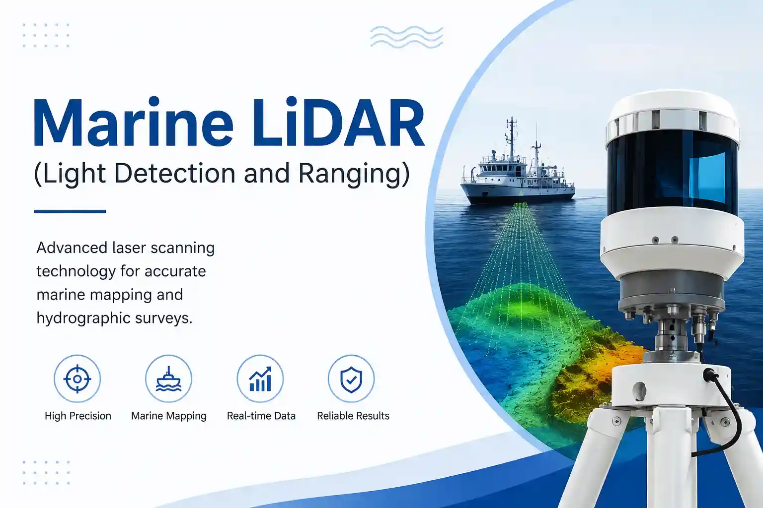
This is the operational reality of marine sensor deployment. When reviewing the latest maritime safety committee notes regarding the advancement of LiDAR – Light Detection and Ranging – the gap between laboratory performance and deck-level reality becomes immediately apparent. The technology is undeniably powerful, but the ocean is an aggressively hostile environment for precision optics.
Operational Observation: Hardware, Weather, and the Messy Reality
Deploying optical sensors on a working vessel is an exercise in managing compromises. The primary friction point isn’t the sensor itself; it’s the environment it has to look through.
Take the wavelength debate, for instance. Most automotive and industrial LiDAR systems operate at 905 nanometers. It’s cheaper, and the silicon photodetectors are mature. But out on the water, 905nm sensors suffer terribly from solar interference. When the sun is low on the horizon, the near-infrared background radiation washes out the detector. I’ve watched point clouds completely drop out during dawn transits because the sensor was effectively staring into an infrared floodlight.
Maritime operators are increasingly pushing for 1550nm systems. The longer wavelength allows for higher pulse energy without violating eye-safety limits, which gives you better range and better penetration through light fog. But 1550nm requires Indium Gallium Arsenide (InGaAs) detectors, which are expensive and run hot. And when I say hot, I mean they require active thermal management. Putting a thermoelectric cooler inside a sealed, salt-blasted enclosure on a vibrating mast is a maintenance headache waiting to happen. If the cooling fails, the sensor’s internal temperature spikes, the laser diode drifts out of spec, and your range accuracy degrades by meters.
Then there is the rain. LiDAR does not like heavy precipitation. A solid downpour creates millions of tiny reflective surfaces in the air. The sensor registers every raindrop as a physical obstacle. In a harbor transit, this results in the object-tracking algorithm throwing up false-positive collision warnings every few seconds. The alarm fatigue sets in fast. If the dashboard is constantly screaming about a phantom kayak that is actually just a heavy squall, the crew will mute the system. Once they mute it, the safety value drops to zero.
Vibration is another silent killer of data quality. A CTV with twin diesel engines running at 1800 RPM generates high-frequency chatter that travels up the aluminum mast. Even if the LiDAR unit itself is ruggedized, the internal micro-electromechanical systems (MEMS) mirrors or spinning motors can develop micro-jitters. This translates to a “smearing” effect in the point cloud. A sharp edge of a concrete dock becomes a fuzzy, three-foot-thick blur. You lose the precise geometric definition that justified the cost of the LiDAR in the first place.
Practical Testing: Simulating the Disconnect
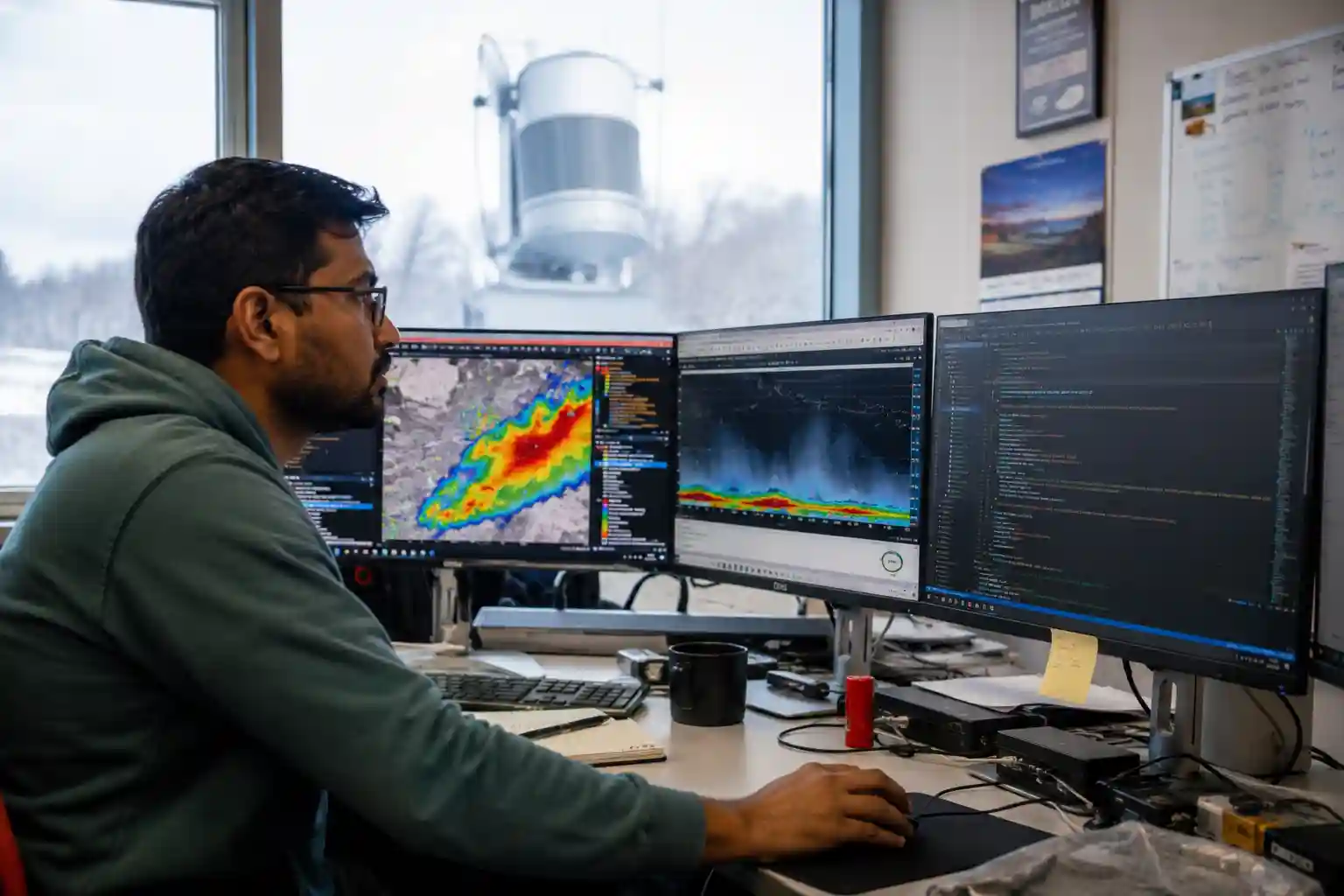
To understand how these environmental factors actually impact vessel operations, we ran a series of bench tests using recorded raw PCAP (packet capture) files from previous transits, feeding them into the vessel’s sensor-fusion processor.
We wanted to see how the system handled the lever-arm effect during heavy pitch and roll. LiDAR data is only as good as the Inertial Measurement Unit (IMU) compensating for the vessel’s movement. If the IMU is mounted on the centerline near the bridge, but the LiDAR is mounted 15 feet forward and 10 feet up on the mast, the physical displacement creates a geometric offset.
In calm water, the software calculates this offset perfectly. But we injected a simulated heavy sea state into the IMU data stream, introducing rapid, violent heave and pitch. The results were frustratingly inconsistent. The sensor fusion algorithm struggled to reconcile the high-frequency mast whip with the lower-frequency hull pitch. The resulting point cloud literally tore apart on the screen. Floating buoys appeared to jump three meters to port, then snap back.
We also tested the latency of the data pipeline. A modern marine LiDAR generates millions of points per second. Pushing that raw data over standard NMEA 2000 networks is impossible; the bandwidth simply isn’t there. You have to use dedicated marine-grade Ethernet, usually M12 X-coded connectors.
During one test, we introduced a 40-millisecond network latency to simulate a heavily loaded Industrial PC (IPC) struggling to process the point cloud while simultaneously running the ECDIS (Electronic Chart Display and Information System) and AIS decoding. That 40-millisecond delay meant that at a vessel speed of 25 knots, the LiDAR overlay on the digital chart was lagging by about half a meter. In open water, half a meter is irrelevant. When you are docking a 30-meter vessel against a steel quay wall in a crosswind, a half-meter discrepancy between the screen and the actual steel is enough to make the captain abandon the screen entirely and stick his head out the window.
The testing confirmed a harsh truth: the hardware is often outpacing the practical software integration. The raw data is beautiful, but turning it into actionable, real-time operational intelligence without overwhelming the ship’s network or the operator’s cognitive load remains a significant hurdle.
Operational Industry Value: Who Actually Benefits?
It is easy to assume that better sensors are universally beneficial, but the cost-to-practicality ratio of marine LiDAR varies wildly depending on the vessel’s operational profile.
Dredging operations and hydrographic survey vessels are the clear winners here. For a dredger working in a confined, shallow channel, knowing the exact 3D geometry of the surrounding seabed and submerged infrastructure is critical. They operate at low speeds, the vessels are relatively stable, and they have the onboard computational infrastructure to process massive point clouds. For them, LiDAR isn’t just a navigational aid; it’s a core operational tool.
Crew Transfer Vessels (CTVs) in the offshore wind sector are another strong use case. They need to push the bow against a turbine boat landing in dynamic sea states. LiDAR provides precise, real-time distance and closing-rate data to the transition piece, allowing the captain to execute the “bump and hold” maneuver with high confidence, even in low visibility. The return on investment is calculated in reduced hull damage and fewer missed weather windows.
Conversely, deep-sea commercial shipping struggles to justify the deployment. A 200,000-ton bulk carrier transiting the Pacific doesn’t need to know the precise 3D shape of a container ship five miles away; standard marine radar and AIS handle that perfectly well. The maintenance burden, the power draw, and the cooling requirements for the processing units make LiDAR a hard sell for traditional blue-water tramp steamers. The infrastructure requirements on older vessels are simply too high. Running shielded, marine-grade Cat6a cable from the monkey island down through cable trunks that haven’t been opened since the ship was built in 2005 is a shipyard nightmare.
There is also a distinct training burden. Bridge officers are trained to interpret the 2D sweep of a radar PPI (Plan Position Indicator) display. Asking them to interpret a dense, 3D colorized point cloud on a flat screen while simultaneously managing VHF traffic and monitoring engine telemetry requires a fundamental shift in bridge resource management. If the crew doesn’t implicitly trust the display, they won’t use it when the fog rolls in.
Comparison Insights: Hardware and Operational Trade-offs
The most common debate in the wheelhouse is LiDAR versus Marine Radar. They are not competitors; they are deeply complementary, but their failure modes are entirely different.
Radar is the undisputed king of bad weather. X-band and S-band radar punch through heavy rain, fog, and sea spray with relative ease. But radar struggles with low Radar Cross Section (RCS) targets. A fiberglass fishing boat, a floating shipping container, or a wooden pallet in the water might not show up on radar until you are dangerously close. LiDAR, on the other hand, will map the exact geometry of that floating pallet from a mile away, provided the air is clear. Fusing the two data streams is the holy grail, but aligning a 2D radar sweep with a 3D LiDAR point cloud in real-time requires serious processing power and careful calibration.
Within the LiDAR market itself, the shift from mechanical spinning units to solid-state sensors has changed the physical deployment strategy.
Early marine LiDAR deployments used spinning mechanical units, similar to those seen on early autonomous cars. They provided a full 360-degree field of view. But putting a spinning motor with precision bearings in a saltwater environment is asking for trouble. Salt ingress and biofouling would seize the motors or degrade the bearings within a year. Furthermore, the spinning mass created gyroscopic effects that fought against the vessel’s motion.
Solid-state LiDAR eliminates the spinning motor, relying on internal optical phased arrays or MEMS mirrors. They are vastly more reliable mechanically and can be sealed much more effectively against moisture. The trade-off is the field of view. A solid-state unit typically only sees a 120-degree horizontal arc. To get full 360-degree coverage around the vessel, you now have to mount three or four separate units. This means three or four times the cabling, three times the power draw, and a complex software calibration process to stitch the overlapping fields of view together without creating “ghost” objects in the seams.
Expert Analysis: The Logic and Limits of Sensor Fusion
The underlying logic of deploying LiDAR at sea is driven by the push toward Maritime Autonomous Surface Ships (MASS) and advanced decision-support systems. The IMO’s regulatory scoping exercise for MASS heavily emphasizes sensor redundancy. You cannot rely on a single modality for collision avoidance.
However, the environmental challenges of the marine sector expose the limits of current sensor fusion algorithms. In an automotive environment, the background is relatively static. Roads have lanes, signs are reflective, and the ground is flat. In a marine environment, the background is constantly moving. The water surface is a dynamic, reflective, chaotic mess.
Wave clutter is a massive computational drain. When a LiDAR scans the ocean surface, the breaking waves reflect the laser pulses back to the sensor. The software has to continuously filter out millions of points generated by the water itself to find the actual solid objects. If the sea state increases, the wave clutter increases exponentially. We have seen IPCs throttle down and drop frames simply because the filtering algorithm couldn’t keep up with the volume of spurious returns generated by a choppy sea.
Communication reliability between the sensor and the display is another critical vulnerability. Marine environments are electrically noisy. Generators, bow thrusters, and heavy switching gear create electromagnetic interference (EMI). If the Ethernet cabling isn’t properly shielded and grounded, you get packet loss. A dropped packet in a LiDAR stream doesn’t just mean a blank spot on the screen; it can cause the tracking algorithm to lose its lock on a target, drop the track, and re-acquire it as a “new” object a second later. This track-jumping is highly distracting for the officer of the watch.
Furthermore, the physical degradation of the hardware over time is rarely factored into the initial procurement models. Laser diodes degrade. The optical output drops over thousands of hours of operation. A sensor that easily detects a small buoy at 800 meters on day one might only see it at 600 meters by year three. Without regular, scheduled recalibration and output testing—procedures that are standard for radar and EPIRBs but still maturing for LiDAR—the crew is operating with a false sense of the system’s actual capability.
Realistic Drawbacks: The Ugly Truth of Marine Electronics
No technology audit is complete without a brutal look at the drawbacks. In the case of marine LiDAR, the friction points are highly specific and deeply annoying for the crew and the technical superintendents.
The Biofouling and Bird Problem: Seagulls love sitting on the highest point of the wheelhouse. Unfortunately, that is exactly where the LiDAR is mounted. Bird droppings on the optical window will completely blind a sector of the sensor. Unlike a camera, which might just get a blurry spot, a LiDAR will interpret the dried guano as a solid object sitting two inches from the lens, generating a continuous, localized false alarm.
Connector Corrosion: Even with IP68-rated marine connectors, the reality of deck maintenance is harsh. Deckhands use high-pressure saltwater hoses to wash down the decks. If the dielectric grease inside the M12 Ethernet connector wasn’t applied perfectly during installation, moisture wicks into the pins. You get galvanic corrosion, leading to intermittent data dropouts that are incredibly difficult to troubleshoot. You end up replacing expensive cables because a $2 connector failed.
Dashboard Clutter and Alarm Fatigue: During heavy weather, the sheer volume of false positives generated by sea spray and rain can clutter the ECDIS overlay to the point of unusability. The screen becomes a dense fog of red and yellow hazard markers. If the software doesn’t have an intuitive, easily accessible “weather filter” toggle that the mate can adjust on the fly, the system becomes a distraction rather than an aid.
Thermal Management Failures: As mentioned, 1550nm sensors run hot. In a tropical climate, with the sun beating down on a black-painted mast, the ambient temperature inside the sensor housing can exceed the operating limits of the internal electronics. We have observed systems initiating thermal shutdowns in the middle of a harbor transit in the Middle East, simply because the internal heatsinks couldn’t dissipate the heat fast enough.
The Wiper Blade Paradox: To keep the optical window clean, manufacturers install heavy-duty marine wipers. But the wiper blade itself and the metal arm physically block the laser pulses every time it sweeps across the glass. The software has to be programmed to ignore the returns from the wiper blade, which creates a momentary blind spot in the data. It’s a kludge, but it’s a necessary one.
Installation and Calibration Delays: Mounting a LiDAR isn’t just bolting it to the deck. It requires a precise survey to measure the exact XYZ offset from the vessel’s center of gravity and the primary GNSS antenna. If the vessel goes into drydock and the mast is modified, or if the sensor is bumped by a crane during provisioning, the calibration is ruined. Recalibrating requires bringing in specialized technicians, resulting in operational downtime.
The Human Element in the Wheelhouse
Beyond the hardware and the code, there is the human element. Technology does not operate in a vacuum; it operates in a wheelhouse at 0400 hours, in the freezing rain, with a tired crew trying to bring a vessel alongside.
I recall standing on the bridge of a research vessel during a coastal survey. The LiDAR was performing beautifully, mapping the rocky shoreline with millimeter precision. But the second mate was visibly frustrated. The user interface for the LiDAR overlay was designed by software engineers in a quiet office, not by mariners. The menus were nested, the text was too small to read in the harsh glare of the bridge windows, and adjusting the point-cloud density required taking his hands off the controls to use a mouse.
“It’s great data,” he told me, tapping the screen. “But if I have to look down and click through three menus to turn off the rain filter when a squall hits, I’m not looking out the window. And if I’m not looking out the window, I’m not driving the boat.”
That is the crux of the operational reality. The advancement of technology is undeniable. The point clouds are denser, the ranges are longer, and the solid-state units are more robust than their mechanical predecessors. But the ocean remains undefeated. Salt creeps into the connectors, the sun blinds the detectors, the vibration shakes the mirrors, and the software struggles to separate a breaking wave from a floating log.
For the marine technology sector, the next phase of development shouldn’t just be about increasing the pulse repetition frequency or shrinking the sensor housing. It needs to be about the unglamorous, non-scalable work of operational integration. It’s about building user interfaces that a mariner can operate with wet gloves. It’s about developing self-cleaning optical coatings that actually survive a month in the North Atlantic. It’s about writing filtering algorithms that understand the difference between a rain squall and a solid target without requiring a computer science degree to tune.
Until those friction points are addressed with the same rigor as the laser physics, LiDAR will remain a highly capable, deeply frustrating, and absolutely essential tool for the vessels that rely on it. It is a brilliant piece of technology, constantly fighting a losing battle against the sea, and somehow, through constant maintenance and crew adaptation, still managing to get the job done.