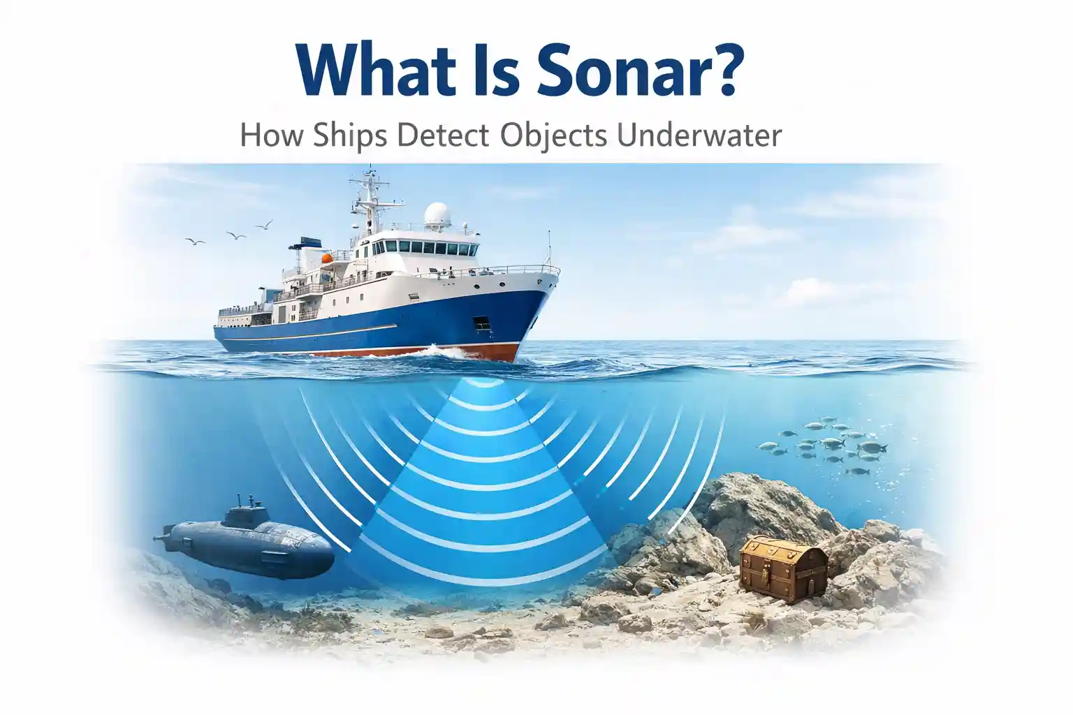
What Is Sonar? How Ships Detect Objects Underwater When the Acoustics Get Complicated in 2026
The multibeam array pushed out its acoustic pulse at 400 kHz, expecting a clean bottom return at forty-two meters. Instead, the processing console threw back a scattered cloud of mid-water returns that looked like a submerged structure until you remembered where the thermocline sat that morning. The operator didn’t reboot the system. They pulled up the latest CTD profile, watched the temperature gradient drop 1.8 degrees over six meters, and adjusted the sound velocity compensation manually. The phantom target dissolved. The seafloor snapped back into focus.
That moment isn’t a glitch. It’s the baseline for asking what sonar actually does in operational conditions. The textbooks explain the physics cleanly: acoustic pulses travel through water, reflect off targets, return to a transducer, and get processed into spatial data. The reality involves water columns that bend sound, hull vibration that drowns out weak returns, marine growth that alters beam patterns, and software that frequently overcompensates for environmental noise until you learn to dial the automatic gain control back yourself. The technology works. It just doesn’t work the way the lab demonstrations suggest.
You don’t deploy a sonar system to find objects underwater by flipping a switch. You deploy it by understanding the acoustic window you’re operating inside, accepting that the data stream will always contain noise, and training operators to separate genuine targets from propagation artifacts. The gap between theoretical sonar performance and field-level detection is where maritime operations actually live. And that gap is wider than most procurement documents acknowledge.
The Acoustic Window Opens, Then Fades
Water isn’t a consistent medium. Sound velocity changes with temperature, salinity, and pressure. In shallow coastal zones, surface heating creates a strong thermocline that refracts acoustic beams upward or downward depending on the source depth and transmission angle. I’ve watched side-scan systems miss pipeline markers that sat just three degrees below the acoustic horizon, only to return clear returns after a tide shift altered the stratification. The system didn’t fail. The physics did exactly what the ocean physics models predict. The operator just hadn’t updated the velocity profile in time.
Hardware inconsistencies compound the problem. A flush-mounted hull transducer sounds clean in the builder’s yard. Six months into operations, micro-barnacles, biofilm, and localized paint blistering change the acoustic coupling. The face doesn’t look rough to the naked eye, but it scatters high-frequency energy enough to raise the noise floor. The automatic target detector starts flagging biological layers and plankton swarms as debris. You can’t solve that with a firmware patch. You schedule a dive inspection, brush the face with non-abrasive pads, and re-run a calibration sweep in known water depths.
Installation geometry matters more than most vendors advertise. You can’t mount a forward-looking imaging array directly above a bow thruster tunnel without getting constant turbulence noise during low-speed maneuvering. You can’t run coaxial feeds parallel to high-current propulsion cables without picking up harmonic interference that shows up as vertical striping on the display. Routing constraints force compromises. Sometimes you accept a slightly higher mounting position to avoid vibration coupling. Sometimes you accept a minor beam shadow because the alternative requires cutting through primary structural bulkheads. The sonar system adapts. You just learn where it’s blind.
Connectivity between the transducer and the processing console rarely stays clean. Fiber optic runs solve most latency issues, but wet-mate connectors degrade. I’ve opened junction boxes on offshore survey vessels where moisture had wicked along the cable jacket, leaving a conductive path that intermittently grounded the return signal. The console didn’t crash. It just started dropping pings at irregular intervals. The operator learned to watch the ping-rate indicator and manually trigger a buffer flush when the display froze. It’s not elegant. It’s necessary.
Field Trials and the Noise Problem
I set up a controlled trial in coastal waters using a calibrated sphere target and a multi-frequency imaging sonar to track how detection thresholds shifted under changing sea states. The setup was straightforward on paper: tow the target at a fixed depth, maintain a steady vessel speed, and log return strength across frequency bands. Within twenty minutes, wake turbulence and surface chop introduced enough backscatter to raise the noise floor by nearly eight decibels. The automated detection algorithm compensated by boosting receiver sensitivity, which in turn amplified mid-water biological returns and created false targets in the water column.
The confusion wasn’t immediate. It accumulated. Operators watching the display for two hours before I adjusted the processing parameters started logging phantom contacts. One flagged a submerged object at fifteen meters depth that turned out to be a dense patch of kelp drifting through the acoustic path. Another dismissed a faint bottom return as side-lobe interference until the vessel drifted and the contact resolved into a concrete wreck fragment. The system wasn’t unreliable. It was just optimized for clean-water testing conditions that don’t exist outside a controlled basin.
Set up friction shows up quickly when you try to synchronize sonar data with external positioning. RTK GPS gives you centimeter-level surface accuracy, but acoustic timing relies on sound velocity calculations that shift hourly in tidal zones. I’ve seen survey teams spend more time reconciling positional drift from outdated sound speed profiles than actually mapping the seafloor. The software will interpolate, but interpolation isn’t detection. It’s guesswork with a confidence interval. Operators who know the difference learn to pause data collection, drop a CTD, and refresh the velocity matrix before continuing.
Monitoring inconsistencies becomes obvious during heavy traffic periods. When multiple vessels operate in the same acoustic band, you get pulse interference. Modern systems include frequency-hopping protocols to avoid cross-talk, but those protocols don’t always align with older commercial echo sounders or fishing fleet sonar units. The display fills with overlapping arcs and ghost returns. You filter by pulse repetition rate. You narrow the acceptance window. You accept reduced coverage in exchange for cleaner returns. It’s a practical compromise that never makes it into the product brochure.
Who Actually Depends on This, and Who Pays for It
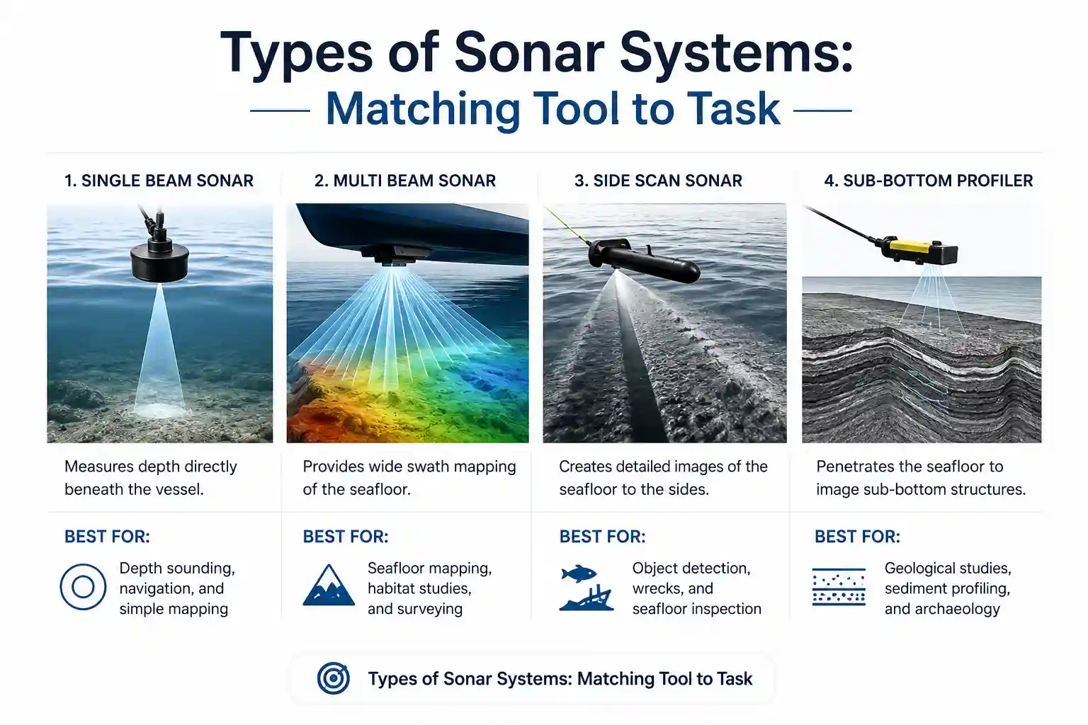
Offshore construction crews rely on forward-looking sonar to verify pipeline burial depth and avoid uncharted obstructions during trenching. Port authorities use high-frequency side-scan to monitor channel clearance after storm surges. Salvage teams depend on dual-frequency imaging to differentiate between scattered debris and intact structural components in low-visibility wrecks. The benefit isn’t theoretical. It’s operational risk reduction. You don’t drop a remotely operated vehicle into forty-meter visibility if you don’t have a reliable acoustic preview.
Smaller operators struggle more. A regional dredging contractor with a legacy single-beam system won’t see immediate returns from upgrading to a multi-frequency multibeam array unless they also invest in positioning integration, velocity profiling, and trained operators. The hardware cost is only the entry fee. The real burden sits in calibration schedules, software licensing renewals, and the downtime required to run verification sweeps. I’ve watched procurement teams approve equipment purchases while deferring the training budget. The system gets installed. Nobody knows how to interpret the side-lobe artifacts. The data sits in archives until a consultant reviews it six months later.
Training doesn’t follow a standard curriculum. You can’t certify someone in acoustic data interpretation the way you certify them in basic radar operation. Sonar requires pattern recognition built over hundreds of logged hours. Operators learn to identify fish layers by their diffuse, horizontally drifting signatures. They learn to recognize bottom reverberation by its rapid decay and symmetrical scatter. They learn when a faint vertical return is a wreck fragment and when it’s a thermocline reflection bending around a submerged slope. That knowledge isn’t packaged in vendor training modules. It’s built through repeated exposure and occasional mistakes.
Infrastructure requirements scale with deployment complexity. Deep-water operations need low-frequency arrays to penetrate hundreds of meters of water column, sacrificing resolution for range. Shallow-water mapping demands high-frequency beams that resolve fine detail but attenuate quickly. You can’t bridge that gap with a single system. Vessels that operate across both environments carry dual setups, which means double the cabling, double the calibration routines, and double the maintenance burden. The cost-to-practicality ratio only works when the vessel’s mission profile demands both. Otherwise, you’re paying for capability you’ll never fully utilize.
Coastal Work Patterns vs. Offshore Acoustic Behavior
Coastal sonar deployment operates in a high-clutter environment. Tidal currents shift sediment plumes. River outflow alters salinity gradients. Commercial traffic introduces constant acoustic interference. The systems behave differently here than they do in open ocean deployments. High-frequency imaging arrays excel in clear, shallow water but struggle when suspended sediment raises backscatter levels. I’ve seen side-scan returns degrade into a uniform gray noise field after a spring tide stirred up fine silt, even though the water column looked visually clear from the bridge.
Offshore deployments trade clutter for attenuation. Sound travels farther, but returns weaken with distance. Low-frequency arrays maintain detection range at the cost of resolution. The processing software compensates by applying aggressive noise reduction, which can inadvertently smooth out small but operationally significant targets. You don’t notice the smoothing until you overlay the acoustic map with a previous survey and realize a subtle seafloor feature disappeared during processing. The operator learns to adjust the display gain manually, accepting a noisier baseline in exchange for preserving target edges.
Commercial systems handle these shifts with automated frequency switching and adaptive beamforming, but the algorithms still lag behind human pattern recognition. A seasoned operator will notice a consistent anomaly that the software dismisses as reverberation because the return angle doesn’t match the programmed threshold. Military sonar arrays include more sophisticated filtering and longer acoustic integration times, but commercial vessels rarely justify that expense. The difference isn’t capability. It’s budget allocation and operational tolerance for uncertainty.
Older infrastructure compounds these limitations. Vessels retrofitted with modern sonar processors often run through legacy signal converters that introduce phase distortion. You don’t see the distortion on the screen. You see it in positional drift when the acoustic timing doesn’t align with the positioning system. Engineers typically trace the problem back to a mismatched baud rate between the transducer controller and the integration gateway. The fix requires a firmware downgrade or a hardware interface replacement. Both take time. Neither appears in the deployment timeline.
Why the Physics Works Differently on a Rolling Deck
Acoustic propagation follows predictable equations in still water. Ships don’t operate in still water. Roll, pitch, and yaw alter the transducer’s orientation with each pulse. Modern motion reference units compensate for this by applying real-time attitude corrections, but the correction relies on precise sensor alignment. If the motion reference unit isn’t calibrated to the exact center of rotation of the hull, the attitude correction introduces angular errors that accumulate over longer survey lines. The data doesn’t fail. It just tilts incrementally until you notice the bathymetry doesn’t align with known control points.
Environmental challenges don’t wait for ideal conditions. Rain hitting the water surface creates a noise layer that masks shallow returns. Wind-driven surface bubbles scatter high-frequency energy before it penetrates the water column. Heavy seas increase hull slap vibration, which couples directly into the transducer mounting structure. You can isolate the transducer with acoustic dampening pads, but dampening adds weight and shifts the resonant frequency. Sometimes the fix introduces more interference than it removes. Operators adapt by adjusting ping timing to avoid the wave trough, or by switching to a lower frequency band during heavy chop.
Hardware degradation is cumulative. Transducer faces develop micro-fractures from repeated pressure cycling. Cable insulation stiffens in cold water, cracking during flex. Connector seals compress over time, allowing microscopic moisture ingress that increases impedance. You won’t catch these issues during a quarterly functional test. You’ll catch them when the system starts returning inconsistent target strength values across identical passes. The maintenance response involves pulling the unit, running impedance tests, resealing wet-mate connections, and verifying face flatness with a precision straightedge. It’s not glamorous. It’s what keeps the acoustic window open.
Communication reliability within the vessel network matters more than external uplink speed. Sonar data streams are heavy. Uncompressed multibeam returns can push multiple gigabits per hour through onboard networks. If the vessel’s data switch isn’t configured with proper QoS routing, sonar packets compete with radar feeds, AIS traffic, and CCTV streams. The result isn’t system failure. It’s delayed display refresh and dropped pings during high-traffic periods. Network segmentation solves the problem, but it requires upfront planning and a technician who understands maritime data architecture, not just enterprise IT routing.
Documented Friction Points and Operational Drag
The friction doesn’t arrive as a catastrophic failure. It accumulates in the margins, and it compounds during extended deployments.
Corrosion attacks the mounting hardware first. Stainless steel brackets in saltwater environments develop crevice corrosion where paint coverage is incomplete. I’ve seen transducer cradles seized by oxidized fasteners, requiring torch cutting to remove during dry-dock. The acoustic performance didn’t degrade. The maintenance burden did. Replacement brackets cost more because they require marine-grade alloys and precision machining to maintain face alignment.
Maintenance intervals compress faster than operational planners expect. A quarterly calibration cycle looks reasonable in temperate waters. In tropical or high-particulate environments, that cycle needs monthly adjustment. The transducer face collects biofilm faster. The CTD sensors drift from biofouling. The velocity profiles require more frequent updates. You don’t skip the maintenance. You just accept that operational windows shrink.
Dashboard clutter becomes a real hazard when multiple sonar feeds run simultaneously. Forward-looking, side-scan, downward-looking multibeam, and hull-mounted obstacle avoidance arrays publish to the same console. During complex maneuvering near mooring lines or submerged infrastructure, operators scroll through overlapping displays to isolate the relevant frequency. The interface doesn’t fail. It just demands more cognitive filtering than a single watchkeeper can reasonably maintain during active navigation. Smart alert routing helps, but configuring those routes requires deep familiarity with the vessel’s acoustic architecture.
Software usability frustrations surface during firmware updates. A vendor patch might improve noise filtering but change the target export format enough to break compatibility with third-party survey software. The integration team has to roll back the update or rebuild the data pipeline. Both options introduce delays. Neither option appears in the original deployment schedule.
Operator learning curves don’t flatten quickly. Reading sonar returns requires understanding what the system can’t see as much as what it can. Side-lobe artifacts, surface reverberation, multipath reflections, and biological noise all mimic real targets until you learn the visual signatures. New operators often overtrust the automated classification algorithms. Experienced operators treat the algorithms as suggestions and verify anomalies against positional data, water column profiles, and historical returns. That trust calibration takes time.
The Compromise Between Theory and Deck-Level Reality
You don’t buy sonar to get perfect data. You buy it to get reliable enough data to make operational decisions without exposing the vessel or crew to unnecessary risk. The technology provides that, but only when integrated into existing workflows with realistic expectations about environmental interference, hardware degradation, and human interpretation limits.
Successful deployments don’t chase maximum theoretical performance. They optimize for consistency. They accept that acoustic returns will fluctuate with sea state, that calibration drifts with temperature, and that software filters will occasionally suppress weak but valid targets. The operators who succeed are the ones who understand the system’s failure modes before they happen. They keep spare calibration weights in the survey store. They carry non-conductive cleaning tools for transducer faces. They know how to manually override automatic gain control when the algorithm starts chasing noise.
The ocean doesn’t standardize. Neither does sonar performance. Maritime engineering research from coastal laboratories consistently notes that acoustic detection thresholds shift by ten to fifteen percent under moderate turbidity and thermal stratification. NOAA’s acoustic propagation models confirm that sound velocity errors of just half a meter per second can introduce positional inaccuracies that compound over survey distances. IMO guidelines for hydrographic operations acknowledge that equipment performance claims apply only under controlled conditions. The real work happens outside those conditions.
What is sonar? It’s an acoustic tool that measures distance through time delay and interprets structure through return strength. How do ships detect objects underwater? They emit pulses, capture reflections, process the timing and amplitude, and filter out everything the environment throws back. But the actual practice involves compensating for thermoclines, managing wake noise, recalibrating for biofouling, and accepting that the display shows probability, not certainty. The system extends human perception underwater. It doesn’t replace it.
Operators who understand that distinction stop treating sonar as an automated truth machine. They treat it as a dynamic sensor that requires continuous calibration, environmental awareness, and skeptical interpretation. That mindset doesn’t scale neatly into marketing materials. It survives in logbooks, calibration sheets, and quiet conversations between surveyors on the night shift. It’s the part of the technology that can’t be simulated. It’s the part that actually matters when the visibility drops and the water column stops behaving like a textbook.